Home >> Products >> Thermal Solutions >> Thermal Interface Material >> LW-9389
A Board Test of LW-9389 TIM Thermal Resistance and Conductivity Measurement Apparatus
STEP 1.Have a copper foil which has the same size as the board sample
and covered thermal grease on both sides of the contact surface.
Record the following data by PC-based data acquisition software.
Calculate the referred thermal impedance(I(ref), ℃*cm²/W)
| Th | Tc | P | Q | R | I(ref) |
| ℃ | ℃ | psi | W | ℃/W | ℃*cm²/W |
| 80.00 | 75.43 | 66.12 | 61.91 | 0.074 | 0.476 |
Measuring and calculated parameters
Th: Hot surface temperature;
Tc: Cold surface temperature;
P: Press load;
Q: Heat flux;
R: Thermal resistance;
I: Thermal impedance;
STEP 2.
The sample is covered by the same thermal grease as STEP 1 on both sides of contact surfaces
and record the following data.
Calculate the total thermal impedance(I(total), ℃*cm²/W)
| Th | Tc | P | Q | R | I(total) |
| ℃ | ℃ | psi | W | ℃/W | ℃*cm²/W |
| 79.98 | 50.42 | 66.10 | 27.60 | 1.071 | 6.910 |
STEP 3.
The thermal impedance of the Board (I(board)) is the difference between I(total) and I(ref)
6.910-0.476=6.434 (℃*cm²/W)
For the thickness of a hard specimen, it is measured by an external micrometer,
and key in the value: t=1.157 mm。
The correlation between apparent thermal conductivity(K), thermal impedance(I) and specimen thickness(t):
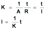
After calculation and unit conversion, we will have the apparent thermal conductivity (K)=1.80 W/m*℃。
Back to LW-9389 specification